

Principles of LBS
2024-05-21

Long-distance VID (above) introduced the definition and trade-offs of VID. In the trade-off section, we discussed that for AR-HUDs, shorter VIDs and distant objects to be indicated can lead to frequent focusing of the driver's eyes, causing fatigue and dizziness[1]. Additionally, shorter VIDs can also result in misalignment between virtual and real images[1]. Therefore, AR-HUD products need to match longer VIDs, typically ranging from 7m to 10m, and sometimes up to 10m to 15m[2]. However, long-distance VIDs also have certain drawbacks, which will be the focus of this article.
Drawbacks of Long-distance VID
(1) Increased Volume
As mentioned in the previous discussion on virtual image distance (VID), VID is related to the system's optical distance (the distance between two lenses plus the distance between the small lens and the PGU). In other words, if one wishes to achieve a long VID while ensuring image quality, it is necessary to increase the system's optical distance, which will result in an overall increase in the volume of the HUD[3]. For example, compared to the traditional W-HUD, which typically has a volume of only 3 to 6 liters, AR-HUDs with long VIDs may have a volume of around 10 liters, or even up to 20 liters. Due to the limited space behind the dashboard in vehicles, the large volume of AR-HUDs has become one of the reasons limiting their application[3].
(2) Optical Design Challenges
Long-distance VIDs usually lead to increased magnification, which poses two problems: optical design challenges and sunlight intrusion. Magnification refers to the ratio of the final image size observed by the human eye after the object is magnified through the lens to the original object size[4]. In HUDs, if we use L to represent the size of the virtual image and P to represent the size of the source (PGU), then the magnification M of the lens can be calculated by the following formula:
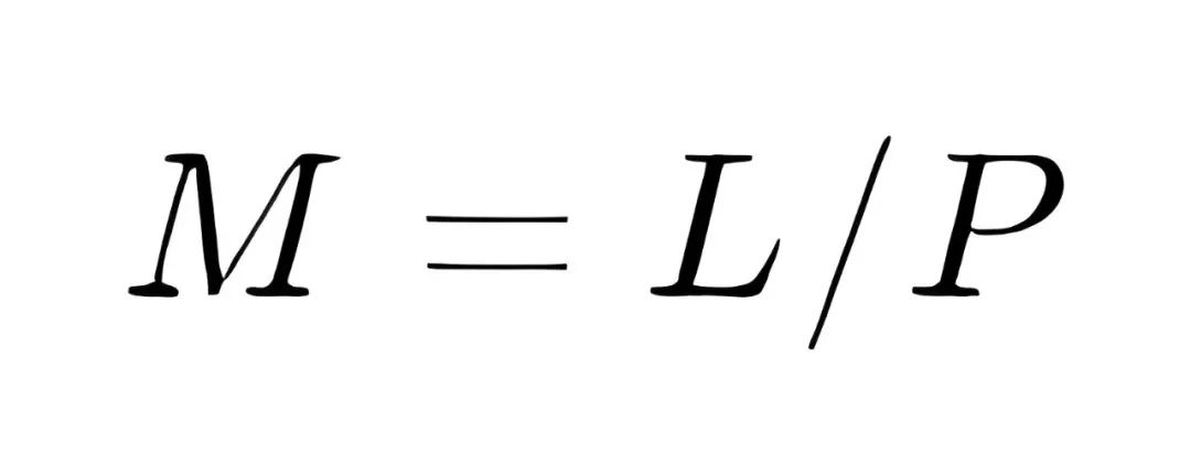
The size of the virtual image L is determined jointly by the field of view (FOV) and the virtual image distance (VID).
![]()
Combining the two equations above, we can obtain the magnification factor of the HUD lens:
![]()
Typically, when designing a HUD, the FOV is a constant determined based on the vehicle's performance requirements and installation space (refer to the principles and applications of Field of View, FOV). The size of the source (P), usually determined by the optical engine (PGU), is also a constant. In other words, with FOV and PGU being constants, the magnification factor (M) of the HUD lens is directly proportional to the VID. The longer the VID, the larger the magnification factor.
The higher the magnification factor of the HUD system, the higher the design requirements for the HUD[5]. Taking HUD's dynamic distortion as an example, when the HUD's PGU is a 3.1-inch TFT and the VID is 2.5 meters, the magnification factor of the HUD is about 5 to 7 times. When designing the HUD optics, the dynamic distortion is controlled to below 2mrad. However, when the VID increases to 7.5 meters, the magnification factor of the HUD is 15 to 20 times, roughly three times that of the former. At this point, we still need to control the dynamic distortion to below 2mrad, but with the increase in magnification factor, controlling dynamic distortion becomes more challenging. Additionally, at higher magnification factors, the tolerance requirements for the HUD system are also stricter.
(3) Sunlight Intrusion
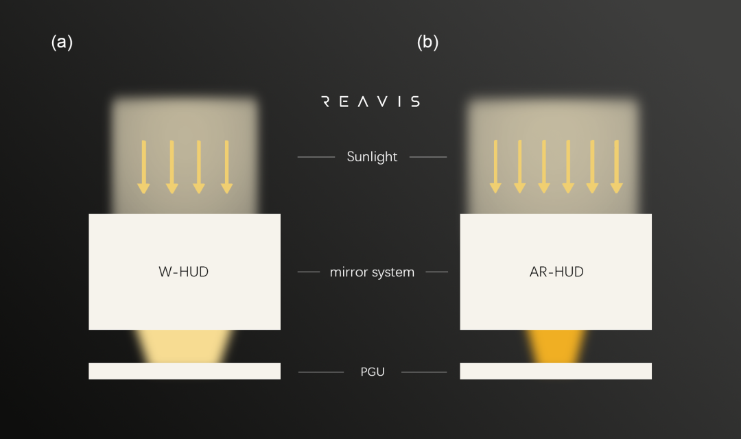
Another issue brought about by long-distance VID is sunlight intrusion, which can cause PGU overheating and consequently lead to HUD failure[7]. Since the optical path is reversible, a higher magnification factor results in a reduced area for absorbing the same amount of sunlight when it reflects off the freeform surface onto the PGU. Consequently, the energy density received at the energy concentration points on the PGU significantly increases.
Moreover, in general, a longer VID implies the need for larger lenses to achieve, meaning more sunlight will be reflected into the HUD's interior by the larger lenses[8]. Taken together, these factors lead to a high-density energy point accumulating on the PGU, similar to igniting a match with a magnifying glass, concentrating all the heat received by the HUD, rapidly raising the PGU temperature, and consequently causing HUD failure[6]. Figure (1) demonstrates a simplified schematic of sunlight entering the HUD's interior under the conditions of short VID for W-HUD (Figure (1)(a)) and long VID (Figure (1)(b)).
Appropriate VID
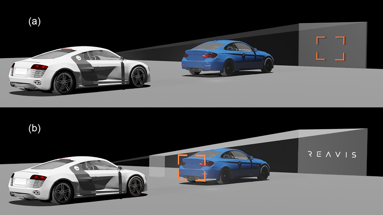
So far, we have discussed only a single value for VID, meaning the HUD has only one imaging focal plane, also known as a single focal plane HUD. Because the virtual image can only be constrained to a fixed-distance plane, single focal plane projection inevitably leads to a distance disparity between the fixed-distance virtual image and the full-depth real-world scene. This distance disparity requires the eyes to continuously switch focus between the virtual image and the real scene, thereby affecting the driving experience. As shown in Figure (2), there still exists a certain gap between the scene projected by the HUD under a single focal plane (Figure (2)(a)) and the ideal scenario of perfect alignment between virtual and real scenes (Figure (2)(b)).
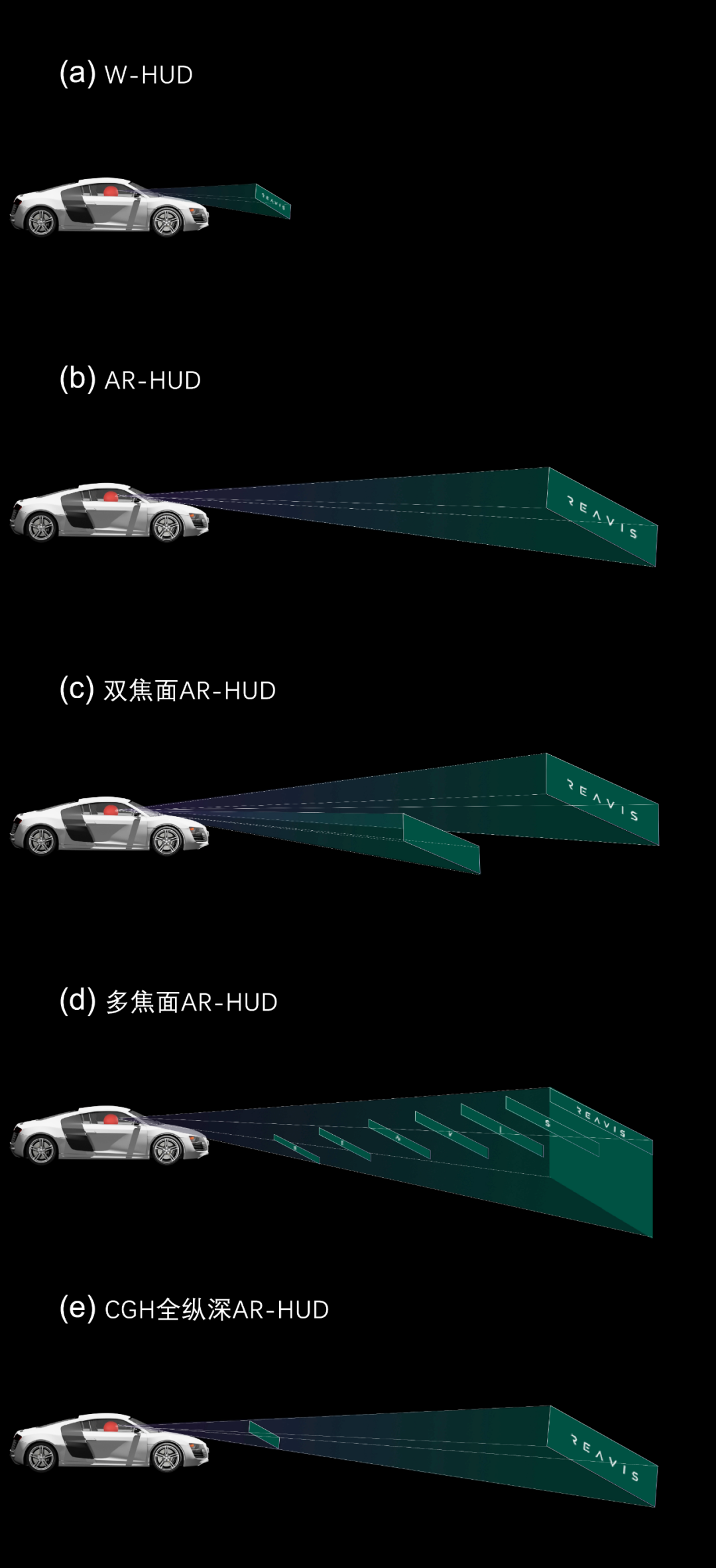
Some commercially available AR-HUDs utilize a dual focal plane system (Figure (3)(c)). Common dual focal plane AR-HUDs set one projection plane with a smaller FOV and shorter VID to display W-HUD content (such as driving information), and another projection plane with a larger FOV and longer VID to display AR content (navigation, driving or pedestrian indicators, etc.). This design is typically achieved through dual optical paths with dual optical engines, or through a single optical path with dual optical engines[9], mainly to balance the VID for continuous display (W-HUD content) and intermittent display (AR content). However, when using a dual focal plane approach, the distance disparity between the virtual image of AR content and the real-world scene still exists. To address this issue and better integrate HUD virtual images with real scenes, 3D AR-HUDs have emerged.
There are various implementation methods for 3D AR-HUDs. For example, the multi-focal plane approach (Figure (3)(d)) utilizes traditional geometric optics to set multiple VIDs and display images on these fixed-distance projection planes[9]. If achieving continuous zoom projection over the full depth (Figure (3)(e)) is desired, it can rely on digital computation holography (CGH) technology, using Liquid Crystal on Silicon (LCoS) phase modulation technology to achieve continuous zoom projection over the full depth. Reconova has been strategically positioned in 3D imaging technology for many years and is currently conducting product research and development for CGH 3D AR-HUDs. Meanwhile, it will soon launch mass-produced multi-focal plane (MF) 3D AR-HUD products.
Combining these two sections, VID is one of the crucial optical parameters for virtual image display devices. A too short VID is unfavorable for observing AR-HUD's display effect and alignment with AR content, while a too long VID can lead to an increase in the volume of HUD devices, raising design and manufacturing difficulties, and posing the risk of sunlight backwash. The most ideal AR-HUD should be a 3D AR-HUD with multiple focal planes.
#Reference:
[1]TEXAS INSTRUMENTS. (2022). "The Importance of a Longer VID for AR HUDs". Technical White Paper
[2]Firth, M. (2019). "Introduction to automotive augmented reality head-up displays using TI DLP® technology". Technical document, May.
[3]Howells,P.J., Brown,R. (2007). "Challenges with displaying enhanced and synthetic vision video on a head-up display". In Enhanced and Synthetic Vision 2007 (Vol. 6559, pp. 155-164). SPIE.
[4]Rekimoto, Jun. (1995). "The magnifying glass approach to augmented reality systems." International Conference on Artificial Reality and Tele-Existence. Vol. 95.
[5]Rankin A, Thompson J. (2015). "Next‐Generation Head‐Up Displays". Information Display, 31(3): 18-21.
[6]Li, Ke, et al. (2020). "Distortion correction algorithm of ar-hud virtual image based on neural network model of spatial continuous mapping." IEEE International Symposium on Mixed and Augmented Reality Adjunct (ISMAR-Adjunct).
[7]Li Z, Zhou X, Zheng YS. (2017). “Design and Research of Vehicle Driving Auxiliary System Based on AR-HUD”. Journal of wuhan university of technology, 41 (6), 924 –928.
[8]Firth, Mike. (2019). "Introduction to automotive augmented reality head-up displays using TI DLP® technology." Technical document, May.
[9]Zhan T, Xiong J, Zou J, Wu ST. (2020). "Multifocal displays: review and prospect". PhotoniX, 1(1), 1-31.