

Principles of LCoS
2024-03-01

LBS is a picture generation unit based on Laser Beam Scanning, known as LBS. LBS achieves its functionality by using a MEMS mirror to precisely control the reflection direction of the laser beam, directing each laser beam to a specific position to form individual pixels on the imaging medium. Due to the high speed of the MEMS mirror, LBS can meet the human eye's persistence of vision effect, rapidly creating dots on the imaging medium to form an image perceivable by the human eye[1].
Persistence of Vision
The principle of LBS imaging is based on the persistence of vision effect. Physiologically, the human eye's persistence of vision means that an image stays on the retina and in the brain for a short period after the image is perceived, usually lasting about 1/16th of a second. Therefore, when continuous static elements are perceived at a sufficiently fast speed, these separate static elements will merge into a continuous dynamic element in our brain[2]. The "marquee" is a classic application of the persistence of vision effect: light sources and a series of static images are placed on a rotating axis, and when the axis rotates quickly, due to the persistence of vision effect, the human eye perceives all the static images as a single smooth dynamic picture (Figure(1)).
Imaging Mechanism of LBS
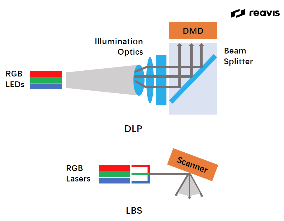
A typical LBS system usually consists of an RGB laser, a MEMS mirror, and a control system[1]. The MEMS mirror is crucial; it is a tiny movable mirror made using Micro-Electro-Mechanical System (MEMS) technology[3]. During operation, the MEMS mirror tilts its surface according to different driving methods (commonly electrostatic or piezoelectric), controlling the deflection of the light beam (Figure(2))[3].

When LBS works, the RGB laser first produces red, green, and blue laser beams, which are coupled to the MEMS mirror's surface through the optical system. The electronic control system then calculates and controls the MEMS mirror's deflection angle and speed based on the information of the image to be displayed, deflecting the laser beam to a specific position where the light beam forms a pixel[1].
After completing the deflection of one pixel, the MEMS mirror repeats the previous steps for the remaining pixels until a complete frame is drawn. Although only one independent pixel appears on the imaging surface at a time, combined with the persistence of vision effect, the human eyes and brain can fully perceive each frame from dot to surface (Figure(3))[1].

Small Size and Flexible Application Scenarios
Due to its unique design and structure, LBS has a compact size advantage. Traditional display technologies (such as DLP) often require multiple lenses and optical elements to focus the image[4], while LBS only needs an RGB laser and one or more small-sized MEMS mirrors for scanning and imaging (Figure(4)). Hence, compared to other imaging systems, LBS does not need a complex optical system for imaging, giving it significant size advantages. Additionally, since LBS is a scanning imaging system, it does not have a fixed imaging focus, allowing it to project clearly at different projection distances and surfaces, providing higher flexibility in application scenarios[4].
Low Power Consumption
Compared to traditional LCD technology, LBS has lower power consumption. Specifically, unlike LCD technology that needs to illuminate the entire panel, LBS uses the MEMS mirror to precisely control the laser scanning path, consuming energy only for the actual display pixels. Additionally, the backlight is usually the largest energy consumer in LCD devices, whereas LBS can form images without an extra backlight, significantly reducing power consumption[5].
High Contrast
Moreover, the laser source of LBS has high monochromaticity, concentrating the projected energy to produce brighter, clearer, and more saturated colors[6].
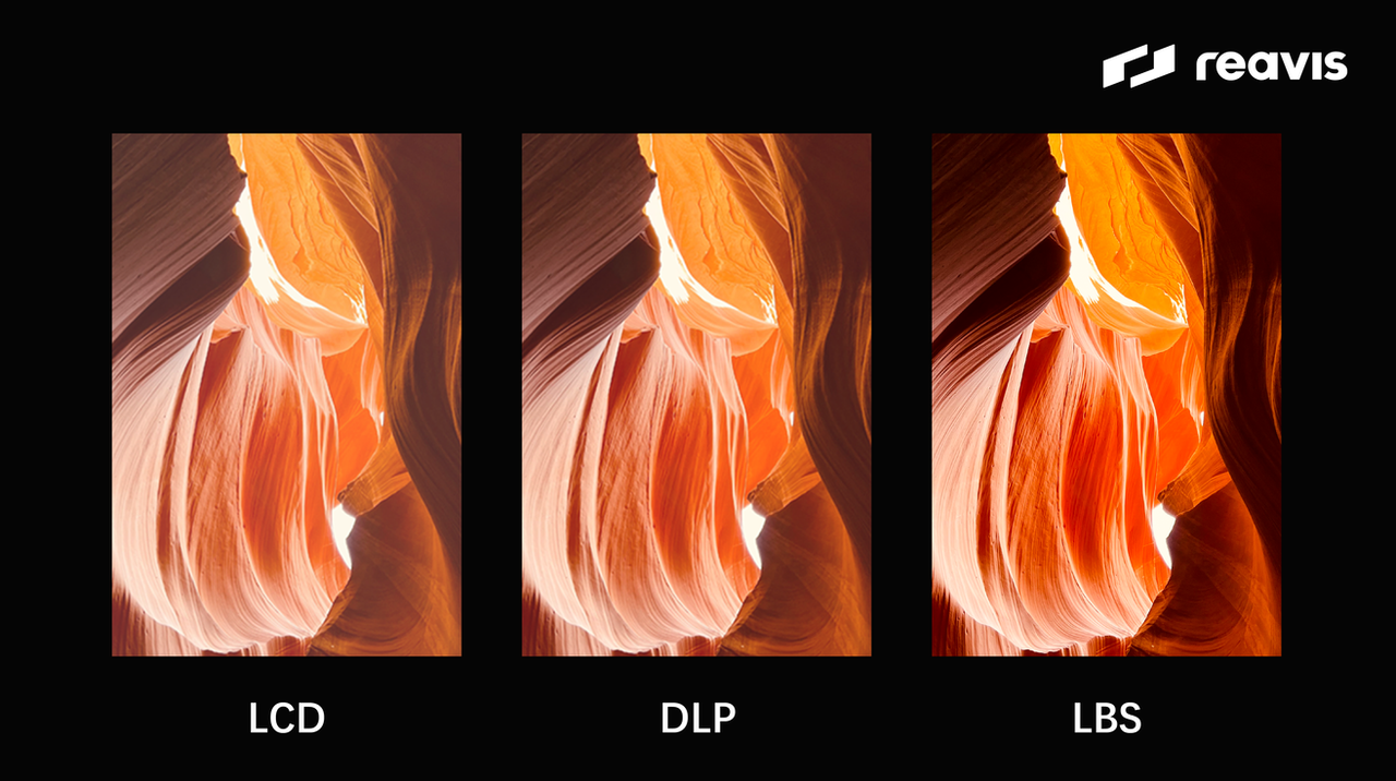
Traditional DLP and LCD cannot control each micro-mirror individually during imaging, only lighting up the entire array area at once. In contrast, LBS uses a laser source where the beam moves point by point, illuminating only a small area at a time to form the required image. By adjusting the laser beam's scanning path and intensity, the brightness of each point in the LBS image can be controlled. As Figure(5) shows, this results in greater brightness differences between bright and dark areas, enhancing the image contrast and providing better visual performance.
Better Color Performance
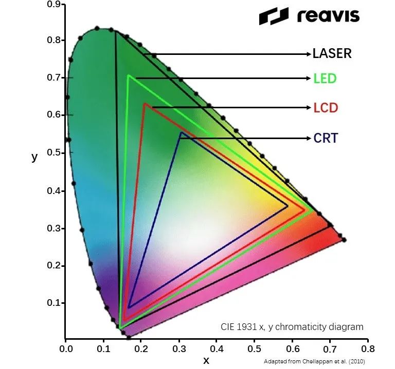
LBS can cover a wider color gamut. Its core light source is the laser, and one of the characteristics of the laser light source is its ability to output pure narrow-band spectrum, meaning better monochromaticity. Therefore, the colors produced have higher color purity. The chromaticity triangle area formed by red, green, and blue in the LBS laser light source is larger, indicating a larger color gamut (Figure(6)). In other words, LBS display devices can show more colors, bringing richer colors and more natural and delicate color transitions[7].
Despite the smaller size and lower power consumption of LBS, along with better contrast and color performance, it also has disadvantages in imaging and application due to its laser and imaging characteristics.
Speckle
Laser sources produce highly coherent light, and when laser light scatters upon hitting a rough surface, electromagnetic waves interfere with each other in space, forming a speckled pattern of random intensity and phase distribution. This irregular pattern, captured by the human eye, is known as laser speckle. Laser speckle can create bright and dark spots on the entire display screen, giving it a "frosted glass" texture, affecting image clarity (Figure(7))[8].
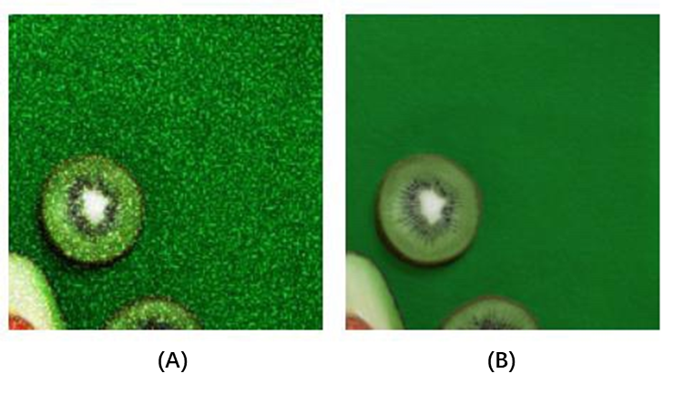
To reduce the negative impact of speckle, additional methods are needed to decrease the coherence of the emitted laser light or perform time-division multiplexing of speckle. However, the design of speckle elimination methods is complex and requires high precision, which may impact system image clarity and brightness, and thus, no widely-used speckle elimination solution exists yet[9].
Distortion
Due to the scanning method and optical characteristics, LBS imaging may have geometric or color distortions. The MEMS mirror's scanning speed changes during scanning, usually slowing down at the edges, and when scanning away from the center, the increased scanning angle may cause the image edges to bend or stretch, resulting in geometric distortion. Additionally, the different wavelengths of laser colors may focus at different positions, leading to color separation or blurring at the edges. The non-linear scanning speed can also cause inconsistent brightness in different image parts, known as color distortion[10].
Difficulty Achieving High Resolution
LBS uses the persistence of vision effect for imaging, and the resolution of the image is closely related to the MEMS scanning mirror's scanning rate. For LBS, all pixels need to refresh at least 20 times per second to meet stable image display. To achieve the same HD1080 display effect (1920*1080 resolution), the MEMS resonance frequency needs to increase from VGA format's 18kHz[1] to 40.5kHz[11]. The MEMS scanning mirror struggles to maintain such a high scanning frequency, thus limiting LBS's resolution[4].
Unstable Colors
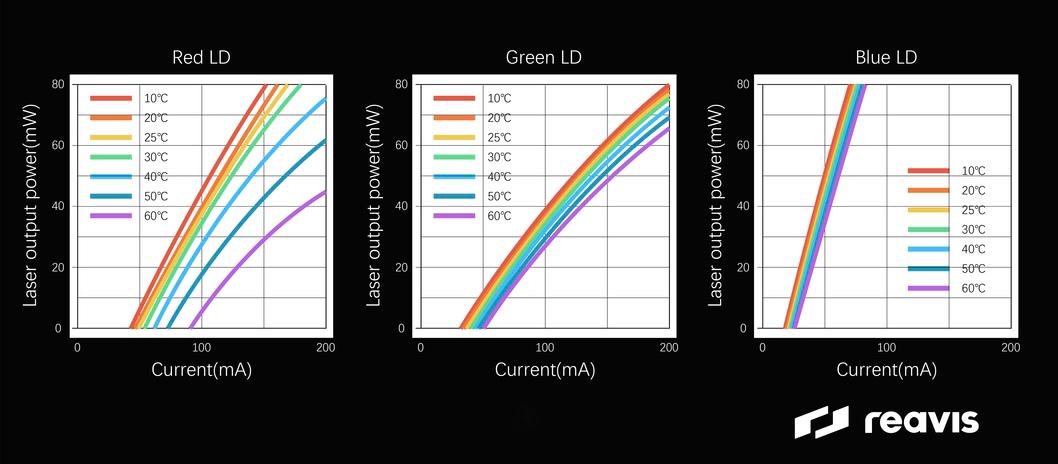
LBS uses lasers, and RGB lasers are sensitive to temperature. The output power of RGB lasers changes with temperature, and while the blue laser remains stable, the red and green lasers exhibit significant temperature drift above 40°C (Figure(8)). This temperature drift causes wavelength shifts, unstable modes, and even malfunction of the laser, affecting the color stability[12].
Current Applications
LBS has various applications in different fields. In AR and VR, LBS systems can achieve compact and lightweight designs, providing immersive visual experiences for users. In 3D scanning and imaging, LBS can generate detailed 3D models of objects or environments, useful for industrial design and cultural heritage preservation. In lidar sensing, LBS is used for distance measurement and creating detailed 3D maps of the surroundings. Additionally, due to higher contrast and better color performance, LBS is applied in cinemas and large outdoor displays[13].
Automotive Applications
In automotive applications, LBS can be used in head-up display (HUD) systems, expanding HUD technology paths by reducing size and lowering the risk of sunlight backscatter. Due to its compact size, LBS can theoretically solve the volume issue of HUD PGUs, achieving a larger field of view (FOV) in the same volume. Since LBS is a projection technology requiring a diffusion film for primary imaging, the high-energy density sunlight converged by the HUD optical system does not load on the optical engine, reducing the risk of sunlight backscatter[14]. However, many issues still need to be solved for automotive LBS technology, such as cost, temperature drift, vibration, speckle, and comprehensive automotive reliability certification, so mass production is not yet seen. Therefore, mass production and automotive implementation of LBS without excessive additional measures remain a challenge.
In summary, the structure and laser characteristics of LBS offer advantages in imaging but also pose high challenges and requirements for HUD applications. Understanding the detailed principles of LBS helps better evaluate and optimize its impact on image quality and practical applications.
Reference:
[1]Petrak, Oleg, et al. (2021). "Laser beam scanning based AR-display applying resonant 2D MEMS mirrors." Optical Architectures for Displays and Sensing in Augmented, Virtual, and Mixed Reality (AR, VR, MR) II. Vol. 11765.
[2]Anderson J, Anderson B. (1993). "The myth of persistence of vision revisited." Journal of Film and Video, 3-12.
[3]Wang, Dingkang, Connor Watkins, and Huikai Xie. (2020). "MEMS mirrors for LiDAR: A review." Micromachines 11(5): 456.
[4]LI Zhao, YUAN Weizheng, WU Meng, et al. (2011). "Micro scanning mirrors with laser diode for pattern generation." Acta Photonica Sinica, 40(11): 1625-1629.
[5]Hofmann, Ulrich, Joachim Janes, and Hans-Joachim Quenzer. (2012). "High-Q MEMS resonators for laser beam scanning displays." Micromachines 3.2: 509-528.[6]Niesten, Maarten, Randy Sprague, and Josh Miller. (2008). "Scanning laser beam displays." Photonics in Multimedia II. Vol. 7001.
[7]Tsai, Pei-Shan, et al. (2009). "Image enhancement for backlight-scaled TFT-LCD displays." IEEE Transactions on Circuits and Systems for Video Technology 19.4: 574-583.
[8]Briers, David, et al. (2013). "Laser speckle contrast imaging: theoretical and practical limitations." Journal of biomedical optics 18.6: 066018-066018.
[9]Akram, M. Nadeem, and Xuyuan Chen. (2016). "Speckle reduction methods in laser-based picture projectors." Optical Review 23.1: 108-120.
[10]Dai, K., and Louie Shaw. (2002). "Distortion minimization of laser‐processed components through control of laser scanning patterns." Rapid Prototyping Journal 8.5: 270-276.
[11]Okamoto, Yuki, et al. (2018). "High-uniformity centimeter-wide Si etching method for MEMS devices with large opening elements." Japanese Journal of Applied Physics 57.4S: 04FC03.
[12]Kumano, Tetsuya, et al. (2016). "Ultracompact RGB Laser Module Operating at+ 85 C." SEI technical review 82.
[13]Merlemis, Nikolaos, Anastasios L. Kesidis, etc. (2020). "Measurement of laser beam spatial profile by laser scanning." European Journal of Physics 42.1: 015304.
[14]McDonald, T. Gus, and Pierre Mermillod. (2023). "Speckle mitigation techniques for laser point scanned displays in head-up display applications." Advances in Display Technologies XIII. Vol. 12443.