

Principles of LBS
2024-05-21

In the previous issue on the principles of freeform surfaces, we discussed how the design flexibility of freeform surfaces can effectively correct aberrations, thereby achieving better imaging results. However, this also increases the complexity of the surface shape, leading to greater difficulty in manufacturing and testing. In this issue, we will introduce the manufacturing, testing, and evaluation criteria of freeform surfaces.
Manufacturing Process
In the manufacturing process of freeform surfaces, there are differences in materials and methods between prototype parts (samples) and mass-produced parts, depending on the production purposes.
Prototype parts of freeform surfaces, used for verifying optical designs, are typically machined using single-point diamond turning on materials such as steel or aluminum. Due to the direct machining using high-precision single-point diamond turning, the finished surface shape of the prototype can closely match the design value. However, this method is not suitable for directly machining mass-produced products due to the high cost of single-point diamond cutting technology.
For mass-produced products, the core of the freeform surface mold is machined using single-point diamond turning, and resin material is injected into the mold cavity to obtain mass-produced freeform parts, with the surface shape accuracy of mass-produced parts usually lower than that of prototype parts.
For HUD freeform surfaces, the commonly used injection molding materials include PC (polycarbonate) and COC (cyclic olefin copolymer), both of which are plastics. COC has better stability/durability (including high-temperature resistance) than PC[1]. Under the same conditions, the deformation of the surface shape of mass-produced parts using COC material is usually smaller than that of PC, but COC generally comes at a higher price. Therefore, each material has its own advantages: PC's advantage lies in cost, while COC's advantage lies in stability.
Surface Coating
In the previous issue, we mentioned that freeform surfaces can be either lenses or mirrors. Usually, in optical design, there are certain requirements for the transmittance and reflectance of the original surface, so after the part is machined and formed, optical thin films are deposited on its surface to match the design. Optical thin films can change the transmission characteristics of light waves (such as transmission, reflection, absorption, scattering, polarization, and phase change) and can be divided into dielectric films, metal films, or a combination of both[2].
When freeform surfaces are used in HUDs, the finished freeform surface needs to be coated to improve its reflectance. Generally, the reflectance requirement of freeform mirrors in the visible light band of HUDs is greater than 90%. In AR-HUDs, if the PGU adopts TFT, considering the problem of sunlight backflow, the coating requirements for small curved mirrors are even higher, and they need to consider the infrared band to absorb the infrared part of the sunlight energy.
Surface Measurement
Since the design of freeform surfaces is very precise, we need to measure the formed freeform surface to inspect its deviation from the ideal design value, thereby determining whether the ideal imaging effect can be achieved. The measurement methods of freeform surfaces are divided into point-line and surface types[3].
The point-line measurement method is a relatively traditional surface inspection method, mainly suitable for milling, grinding, and rough polishing stages during the machining of freeform surfaces. The point-line measurement method is relatively simple but has slow measurement speed, low accuracy, and efficiency. Currently, typical point-line measurement methods mainly include three-coordinate measuring machine method (CMM), profile gauge method, and articulated arm contour scanning method.
In contrast, the surface measurement method can directly obtain surface data, with fast measurement speed and high efficiency, but the measurement cost of this method is also relatively high. Interferometry is a typical surface measurement method, which mainly includes white light interferometry, structured light method, computational holography, and tilt wavefront method.
Evaluation Criteria
In the manufacturing process of freeform surfaces, the surface shape will fluctuate due to the tolerance of the production process. If the surface shape error is large, it will greatly affect the imaging quality. By analyzing the collected surface shape data of the formed freeform surface after measurement, we can evaluate the quality of the freeform surface. The common evaluation indicators of freeform surface shape include PV, RMS, and RA values.
PV (Peak to Valley), also known as peak-to-valley value, describes the maximum error of the formed freeform surface shape compared to the design surface shape, usually in units of micrometers (μm). During inspection, we will sample the entire freeform surface at certain intervals (e.g., 0.5 mm). Assuming in the surface shape matrix W(x, y)[4], where x and y are the row and column serial numbers, respectively, Wmax and Wmin are the maximum and minimum values of W(x, y) within the sampled matrix, then PV is the difference between Wmax and Wmin[4].
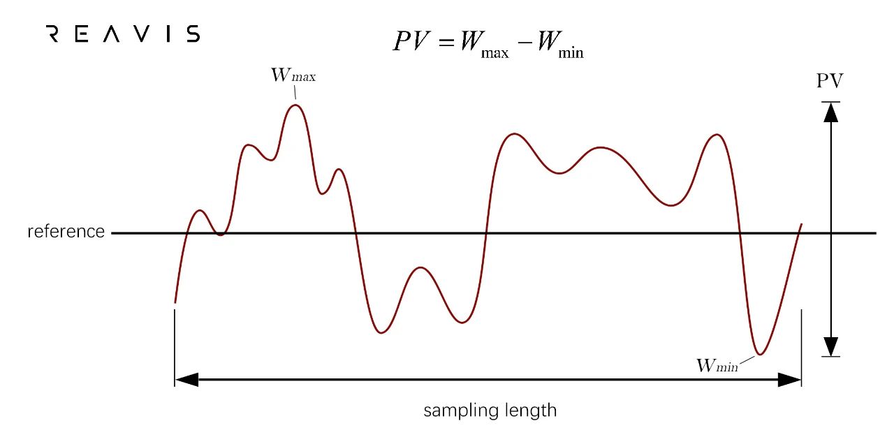
The PV value indicates how closely the freeform surface matches our intended design effect. In actual production, PV is typically correlated with the size of the mirror. Larger mirrors usually result in larger PV values. For instance, in W-HUD systems, mainstream suppliers can typically maintain PV values around 60μm. In AR-HUD systems, where the mirror size increases (to 300mm and above), PV values are usually around 100μm.
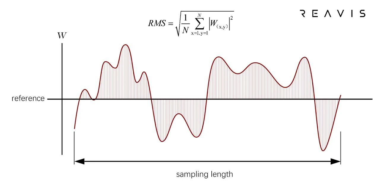
RMS refers to the root mean square of the error values (Residual) between the actual surface shape and the design surface shape at each sampled pixel W(x, y)[5], as illustrated in Figure (2). In HUD applications, the RMS of the freeform surface is generally required to be controlled within 1/6 to 1/5 of the PV value. This ensures relatively stable control of the mirror surface shape and reduces abrupt changes in surface shape. For example, when the PV value is 100μm, the RMS value should be controlled within 20μm.
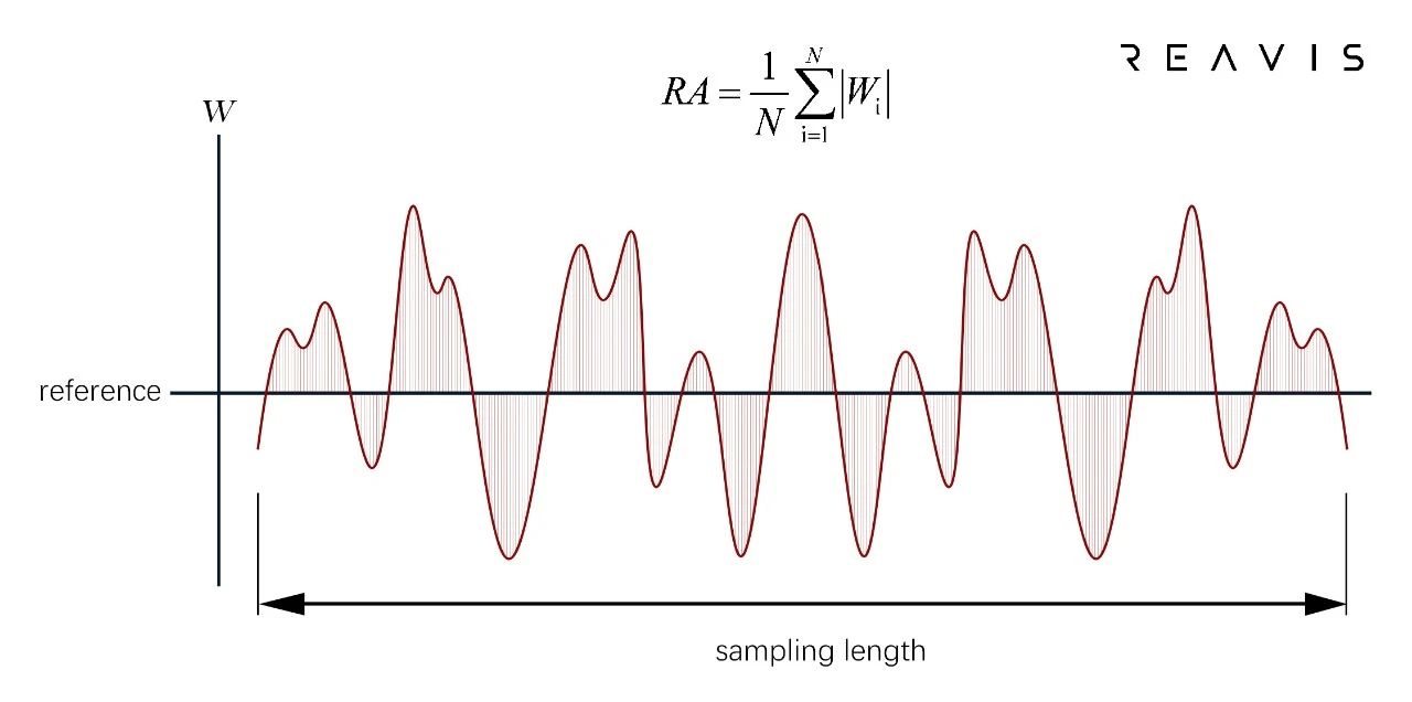
RA describes the surface roughness of the freeform surface, reflecting the characteristics of the micro-geometric shape height of the object surface, usually in units of nanometers (Figure (3)) [6]. The calculation method of RA is to take a sampling straight line within the detected freeform surface, and calculate the average absolute value of the deviation of each sampling point on the straight line from the mean line. Typically, we require RA to be less than 10nm. Excessive RA can cause the virtual image to appear blurry, as if the virtual image were veiled.
PV, RMS, and RA may affect the clarity and distortion of the imaging (including dynamic and static distortions). Generally, the smaller the PV, RMS, and RA values, the closer they are to the ideal imaging effect.
In summary, the high design freedom of freeform surfaces brings its advantages in high performance but also leads to high difficulty and requirements in process design. Understanding the processing, production, and evaluation criteria of freeform surfaces helps to better understand the impact of freeform surfaces on imaging quality, thereby helping us to consider comprehensively from theoretical, simulation, process, and production perspectives during design to ensure the final image quality.
#Reference:
[1]http://www.ccin.com.cn/detail/2066f367bb413825638e86b8d5c6223b
[2]https://www.21ic.com/article/858554.html
[3]Thompson K P, Rolland J P. (2012). "Freeform optical surfaces: a revolution in imaging optical design". Optics & Photonics News. 23(6): 30-35.
[4]Wang Z, Zhai Y, Mei G, etc. (2010). "Design of Flexible Support for Space Optical Remote Sensor Mirror". Optical Precision Engineering. 18(8):1833-1841.
[5]Li M, Wu Q W, Yu F. (2010). "Optimization of the thickness of optical window glass based on thermo-optical analysis". Acta Optics Sinica. (1):210-213.
[6]Cao LX, Li DF. (1990). "Measurement of surface roughness parameter Ra by infrared light scattering technique". Journal of Aeronautics and Astronautics, (4):-B216.